|
|
We've seen the forward kinematics problem. The inverse kinematics
problem is much more interesting and its solution is more useful.
At the position level, the problem is stated as, "Given the
desired position of the robot's hand, what must be the angles at all
of the robots joints?"
Humans solve this problem all the time without even thinking
about it. When you are eating your cereal in the morning you just reach
out and grab your spoon. You don't think, "my shoulder needs to
do this, my elbow needs to do that, etc." Below we will look at
how most robots have to solve the problem. We will start with a very
simple example.
|

|
|
|
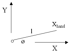
The figure above is a schematic of a simple
robot lying in the X-Y plane. The robot has one link of length l
and one joint with angle Ø. The position of the robot's
hand is Xhand. The inverse kinematics problem (at
the position level) for this robot is as follows: Given Xhand
what is the joint angle Ø? We'll start the solution to this
problem by writing down the forward position equation, and
then solve for Ø.
|
|
|
|
Xhand = lcosØ
(forward position solution) |
|
cosØ = Xhand/l |
|
Ø = cos-1(Xhand/l) |
|
|
|
To finish the solution let's say that this
robot's link has a length of 1 foot and we want the robot's hand
to be at X = .7071 feet. That gives: |
|
|
Ø = cos-1(.7071) = +/- 45
degrees |
|
|
Even for this simple example, there are two
solutions to the inverse kinematics problem: one at plus 45 degrees and one at
minus 45 degrees! The existence of multiple solutions adds to
the challenge of the inverse kinematics problem. Typically we
will need to know which of the solutions is correct. All
programming languages that I know of supply a trigonometric
function called ATan2 that will find the proper quadrant when
given both the X and Y arguments: Ø = ATan2(Y/X). Now we have
the tools we need to look at a more interesting inverse
kinematics problem:

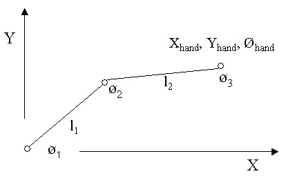
You may have to use your
imagination a bit, but the schematic above is the planar part
of the SCARA robot we discuss in the industrial
robots section. Here's the statement of the inverse
kinematics problem at the position level for this robot: |
|
|
|
Given: Xhand, Yhand,
Øhand |
|
Find: Ø1, Ø2
and Ø3 |
|
|
|
To aid in solving this problem, I am
going to define an imaginary straight line that extends
from the robot's first joint to its last joint as
follows: |
|
|
|
B: length of imaginary
line |
|
q1: angle
between X-axis and imaginary line |
|
q2: interior
angle between imaginary line and link l1 |
|
|
| Then we have: |
|
|
|
|
B2 = Xhand2
+ Yhand2
(by the Pythagorean theorem) |
|
q1 = ATan2(Yhand/Xhand) |
|
q2 = acos[(l12
- l22 + B2)/2l1B]
(by the law of cosines) |
|
Ø1 = q1
+ q2
(I know you can handle addition) |
|
Ø2 = acos[(l12
+ l22 - B2)/2l1l2]
(by the law of cosines) |
|
Ø3 = Øhand
- Ø1 - Ø2 |
|
|
|
| That completes the
solution for Ø1, Ø2 and Ø3
given Xhand, Yhand, Øhand.
Most inverse kinematics solutions at the position level
proceed in a similar fashion. You will use your knowledge of
trigonometry and geometry coupled with your creativity to
devise a solution. The solution given above works as is for
SCARA robots. If you can imagine turning the SCARA robot on
its side, then you will see that the solution above also works
for the positioning components of most six degree of freedom
industrial robots too. The inverse kinematics solution for
Cartesian robots is trivial as all axes are perpendicular by
definition and thus there is no coupling of the motions.
I recently noticed that there are number of folks that have
translated this solution into computer code. If you are
interested I'm sure you can find them with a little searching.
I saw a couple on GitHub.
|
|
|
|
|


